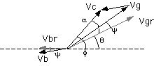
Figure 1. The phaser diagram of the cavity.
change of the cavity temperature --> change of volume of the cavity
--> change
of resonant frequency of the cavity
-->
increase reflected power,
-->
reduction of accelerating voltage
-->
instability ?
<== use movable tuner
to compensate the change of resonant frequency
The resonant frequency of the cavity should be tuned to the RF reference signal. The cavity has movable tuners and one of them are used for this purpose. Figure 1 shows the phaser diagram of the cavity system. (Reference P. B. Willson, 1983, p452-, High energy electron linacs: Application to storage ring rf systems and liner colliders)
Vg is the voltage produced by the generator (klystron). ib is the beam current. Vb is the voltage produced by the stored beam. Vgr and Vbr is the voltage with the cavity tuning angle phi. Vc is the cavity voltage which is the sum of the Vgr + Vbr. The cavity tuning circuit maintain the phase angle psi to be constant (-5 degree) so that the cavity is nearly real for the klystron. At this case the generator power is efficiently fed to the cavity. As the stored current is increased, the angle phi is increased. Figure 2. shows the block diagram of the cavity tuning circuit.
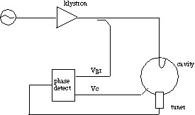
Figure 2. The block diagram of the cavity tuning circuit.
Figure 3 shows the detuning angle phi as a function of the stored beam current.
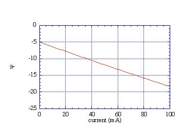
Here we assume
w = 508.58MHz/2p
Q0 = 40000
b = 2
R = 5Mohm
Vc = 500 kV
a = - 5deg
Vrf = 12MV
U = 9MV
f = acos(U/Vrf) = 42deg
q = f-a =47deg
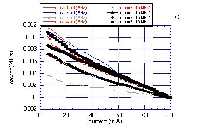
The resonant frequency of the cavity changes 20kHz/mm for the position change of the tuner. Figure 4 shows an example of the tuner position and the stored current.
The movement of the tuner as a function of input RF power is shown in figure 5. The temperature rise is about 10 degree C at 10mm apart from the inner surface near equatorial plane. Water flow rate is about 110 liter / min.